
This tutorial demonstrates how to print electric circuits with Electrifi filament on a typical fused deposition modeling (FDM) desktop 3D printer.
Step 1: Modify the extruder (if necessary)
The Electrifi conductive filament can be printed without any modification of your extruder if the gap between the hobbed gear and the hot end is sufficiently small. Figure 1 shows the filament gets kinked between the gear and hotend if the gap is too large (> 8 mm in this case). This issue can be corrected by inserting a longer Teflon tube (OD = 4 mm and ID = 2 mm) into the hot end barrel to fill the gap. We suggest trying to print Electrify with your printer first, and if this kinking problem happens try replacing your current teflon tube with a longer one.
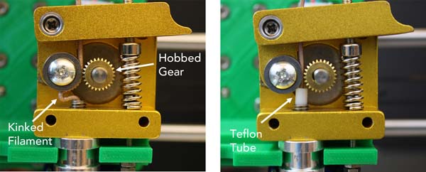
Figure 1 Left: The Electrifi filament is kinked below the hobbed gear. Right: The Electrifi filament is pushed straight through with the support from the Teflon tube.
Step 2: Set the Z-height
For printing Electrifi, we recommend calibrating your printer's Z-axis such that the distance between the nozzle and the bed is around 0.1 mm. Please see your 3D printer's manual for calibration instructions. A standard piece of A4 paper (approximately 0.1 mm thick) can be used as a guide. When slipping the piece of paper between the nozzle and the print bed you should feel the paper drag against the nozzle as you try to pull the paper out. Once the printer is calibrated, you can print on different substrates by changing the Z-offset in your 3D printer software (assuming this setting is available). For Cura, the Z-offset setting can be found under Machine/Machine Settings (Note: we are using the LulzBot edition of Cura, version 17.10). For example, to print on 5-mm-thick foam board, set the Z-offset to 5 mm prior to converting your stl file to gcode. For any substrate, make sure it is taped down to the printer bed so its flat and doesn’t move around.
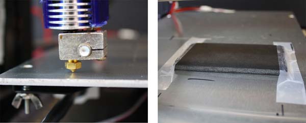
Figure 2. Left: The extruder is at the Home position 0.1 mm from the print bed. Right: The substrate (black foam board) is taped flat to the print bed.
Step 3: Print with Cura
We recommend Cura for slicing and 3D printing because its free, open source, and user friendly. We have optimized a print profile for use with Cura on a Prusa I3 printer. To use the print profile, download and unzip the file, and go to File/Open Profile to load the file into Cura. With our profile settings, it takes 7 minutes to print the circuit shown in Figure 3 (83 mm × 37 mm × 0.5 mm) using a 0.4 mm nozzle, or you can increase the shell thickness to 0.9 mm and nozzle size to 1 mm in order to print the circuit in <4 minutes (see the time lapse video below). Download the stl file below to try it yourself! Note that the Cura profile does not change the Z-Offset, so double check that you have the correct Z-Offset for you substrate before printing.
In our next tutorial, we will turn this circuit into an LED nametag.
Download "cura_electrifi_print_profile"
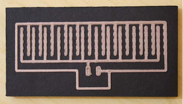
Figure 3. A 3D printed LED nametag circuit on black foam board.