
In this tutorial I'll go through how to make a 3D printed LED matrix display using the WS2812 LED, also called a 'Neopixel' by Adafruit. To learn more about the WS2812, I refer you to the Neopixel Uberguide. Briefly, each one of these chips are individually addressable via a data line that goes from chip to chip across the array. To make a matrix display, you only need three inputs - power, ground, and a data line. Adafruit and others have created Arduino libraries that allow you to easily control the chips, allowing you to scroll text or animations in 24 bit color.
Step 1: Make the LED Matrix in Inkscape
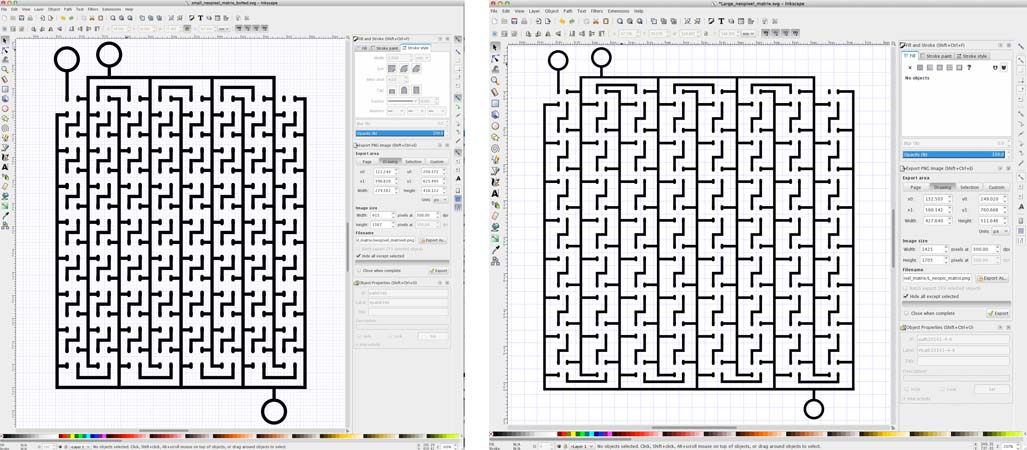
I made the LED matrix display circuit using the same software process as in the "LED Art!" tutorial. It took me about 7 iterations to get this circuit right, but since I could print out each iteration in about 20 minutes with the Electrifi filament, the optimization process was pretty quick. I used the 5050 LED package again, but I removed the two middle pads from the package since the WS2812 doesn't have those. Also, I made some screw-type terminals to make better contact between the wires and the Electrifi Filament. Below is the pictures of the finished circuits and here is the software files. The matrix on the left is pretty close to the smallest (77 by 117 mm) that can be made reliably, while the matrix on the right is about the biggest (120 by 144 mm) I can make with our 3D printer.
Step 2: Place the components and wire up the matrix.
To assemble the matrix you will need the following items:
2. A lithium polymer rechargeable battery and connector.
3. Nuts, bolts, and washers (we used size #6 for this project).
4. An Arduino (we used this Arduino Nano).
5. Some wires (we use 24 AWG) and a wire stripper.
6. A solder reflow station.
7. Foam board.
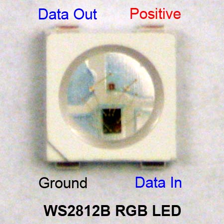
Just like normal LEDs, the WS2812B RGB LED has to be wired up with the right polarity (connections to positive and ground) for it to work. See below for a picture of the WS2812B with its pins labeled. Unlike normal LEDs, you can't just apply power to the WS2812B and have it light up, you have to send a string of voltage pulses through the data pin in order to tell it the intensity and the color of light you want.
I pasted an image of the completed neopixel matrix display below. To place the LEDs, I used a solder reflow tool to heat up the pads before squishing the LEDs into the Electrifi Filament, just as we did in the LED nametag video. Note that for each column of LEDs, the direction of the ground alternates from top to bottom. You can see this in the image because the black chip, which is on the ground side of the LED, switches which side of the LED its on from column to column. This is to allow the data line to snake in an S pattern back and forth across the circuit, allowing for the printing of an LED matrix display in a single layer. This data connection between the LEDs allows you to control their color individually with a microcontroller, but if one LED is placed the wrong way and the data line is cut, all the LEDs after that cut won't light up.
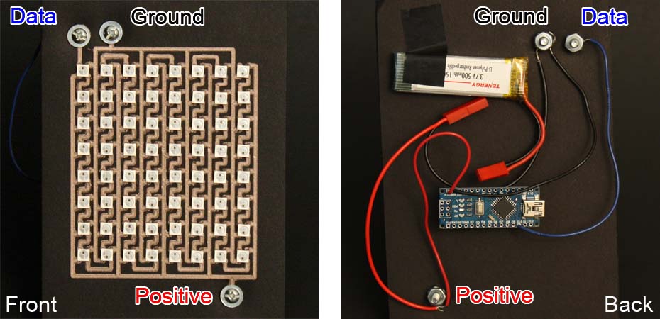
After placing the LEDs, I hooked the matrix up to a lithium polymer ion battery for power, and an Arduino nano as the microcontroller. For other power options, see the Neopixel Uberguide. The Arduino and matrix share the same connections to power and ground where they are sandwiched between two nuts around #6 bolts that I poked through the poster board. The washer on the front of the poster board ensures a low-resistance connection between the filament and the bolt. These bolts are a great way to connect the wires from a battery or external circuit to the printed circuit with a much lower resistance than is possible than just sticking the wire into a pad of filament. I highly recommend this connection method wherever its feasible. Lastly, connect the output pin used from the Arduino to the data line of the matrix display in the same manner. Its not a big deal if you happen to make these connections in a different order.
3. Using the Display
Once you've got the display hooked up, you'll need some code to control it. There are many examples online of code to put text or animations on the neopixel display. Here is one example Arduino sketch that includes text and animation that we modified to our liking: Neopixel_matrix_sprite_arduino.zip. The animations are defined in the Shape.h file. If you want to make your own animations, checkout this online tool. See below for a video showing the animations. Enjoy!