Step 1: Import an image with the desired LED and SMD pad footprints from EAGLE into Inkscape.
For this project I'm using a modified footprint for the 5050 LED package, which is a 5 mm x 5 mm LED, as well as a 2.5 by 5 mm pad. You could actually draw both of these footprints, but I already have them how I want in EAGLE, so I just (a) added them to a schematic in EAGLE, (b) converted the schematic to a board, (c) exported the board as a png image file, (d) imported the image into Inkscape, (e) clicked path -> trace bitmap and path -> break apart to get the individual components. This library has the footprints I used for this step: Multi3D.lbr. To use the library, download it into your EAGLE/lbr directory, and in EAGLE click Library-> Use and choose the Multi3D library. As in the "Making an LED Name Tag" tutorial, I used the image_export script for exporting images from EAGLE to Inkscape.
Step 2: Draw and print the Circuit.
There are lots of ways to go about making LED art, but so far I find it easiest to make an array of LEDs of a desired size, and then place LEDs on the right locations on the array to make an image. In this example I'll make an 8 by 11 array, and later show how to place LEDs on the array to make a space invader.
To make things easier first setup the snap-to grid. I followed the directions in this link. Got to file > document properties > grids and create a new rectangular grid. Change the units to be mm and the x and y spacing to be 1 mm. Next tab over to snap in document properties and choose 'always snap' in the snap to grids section. Finally you'll want to play with the settings in the snap controls bar. If you don't see the snap controls bar,try going to View > Show/Hide > Snap Controls Bar. For me, they show up on the far right of the window. I've got my settings set to those shown below, but feel free to find what works for you.
![]()
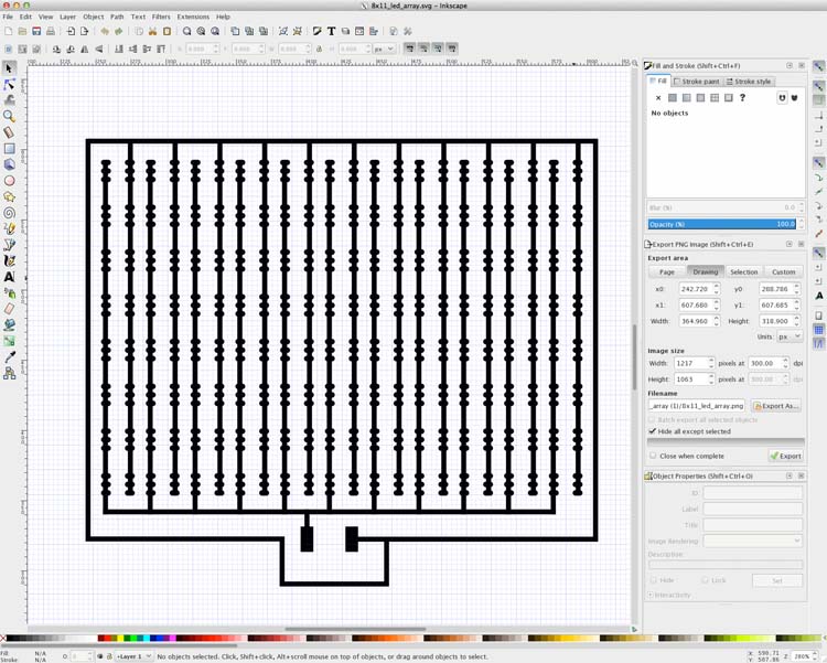
Next, I made a 2x2 array of LED pads spaced roughly 2 mm apart. I copied and pasted these to create row of 8. I then wired them using the 'Draw Bezier curves and straight lines' tool (shift F6). After drawing one line, I changed the stroke style width to 1 mm. I made this the default by clicking Edit > Preferences > Tools > Pen, then clicking "This tool's own style: Take from selection". Once you wire up two rows, you can copy and paste those rows to create the whole array. After wiring up the pads, my LED array looked like the picture below. Finally, I (a) exported it as a jpg to join the lines, (b) reimported it into inkscape, (c) did trace bitmap and exported it as an svg, (d) imported it into blender, (e) resized it and extruded it in the z-direction 1 mm following the same process in the "Making an LED Name Tag" tutorial, (f) exported it as an stl file, (g) imported it into Cura, (h) exported the gcode with the 1 mm nozzle profile settings, and (i) printed it out. We printed it out onto a thin piece of polycarbonate, but poster board or other most hard substrates would work. If you haven't printed with Electrifi Filament before, check out this tutorial.
Step 3: Assemble your LED Art!
To assemble your LED art you'll need the following items:
1. 5050 LEDs
2. Foam board.
3. Some wires (we use 24 AWG) and a wire stripper.
4. A lithium polymer rechargeable battery and connector.
5. A solder reflow station.
Also, optionally you will need:
6. A frame (we got ours from dollar tree).
7. Black cardstock for the mask.
8. A Silhouette Cameo to cut holes in the mask (a laser cutter also works).
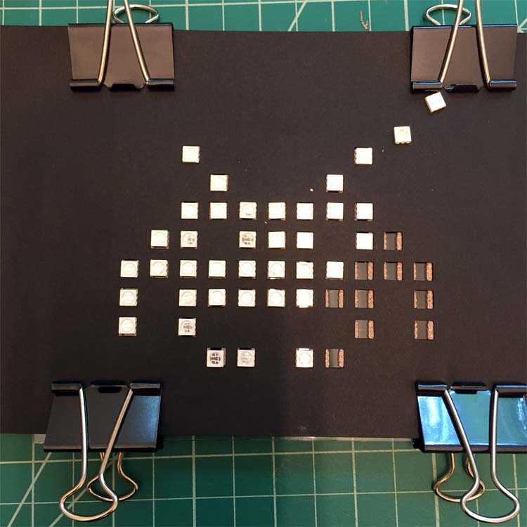
To put the LEDs down on your printed circuit, you can use a solder reflow tool like we outlined in a previous video. Alternatively, you can cut out a mask for the LED placement with a silhouette cameo from card stock. Clip the mask over the circuit, place the LEDs, and clamp the LEDs to the circuit between two rigid pieces of material (e.g. glass, tile, aluminum, ect.) before placing it in an oven at 150 C (300 F) for 5-10 minutes. Below is an image I took during placement of the LEDs onto the printed circuit covered with the black cardstock mask. To make the mask, I drew an image with the art I wanted in photoshop, imported it into the silhouette library, and traced it out in silhouette studio following this tutorial. Here is the images of the masks I used: space_invader_masks.
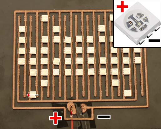
When you are placing your LEDs, make sure that all the cut corners are facing the same direction. In my case they are all in the lower left. The cut end of the LED should go to ground in your circuit, as shown in the picture below.
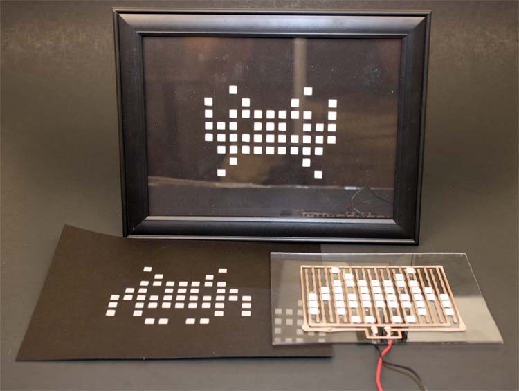
Once the LEDs are placed, attach wires to the pads (as shown in this video) and connect them to a lithium ion battery to light them up. Alternatively, you could connect it to a power supply at 3-4.5 V. Once you've got it working, you might want to finish it off with a nice frame. We used a $1 picture frame from dollar tree as the frame, and some translucent vellum paper as the diffuser. The vellum paper is sandwiched between two masks, making it very easy to align to the LEDs. The picture below shows the diffuser and circuit separately, as well as assembled together in the frame.
Step 4. Enjoy your LED Art!